Dash Camera Power Supply With Ultra Low "Power Off" Consumption (50uA)
A dash camera power supply with a recording timer that keeps the camera running for a while after the engine is switched off, combined with ultra-low power consumption in the off state.
Overview
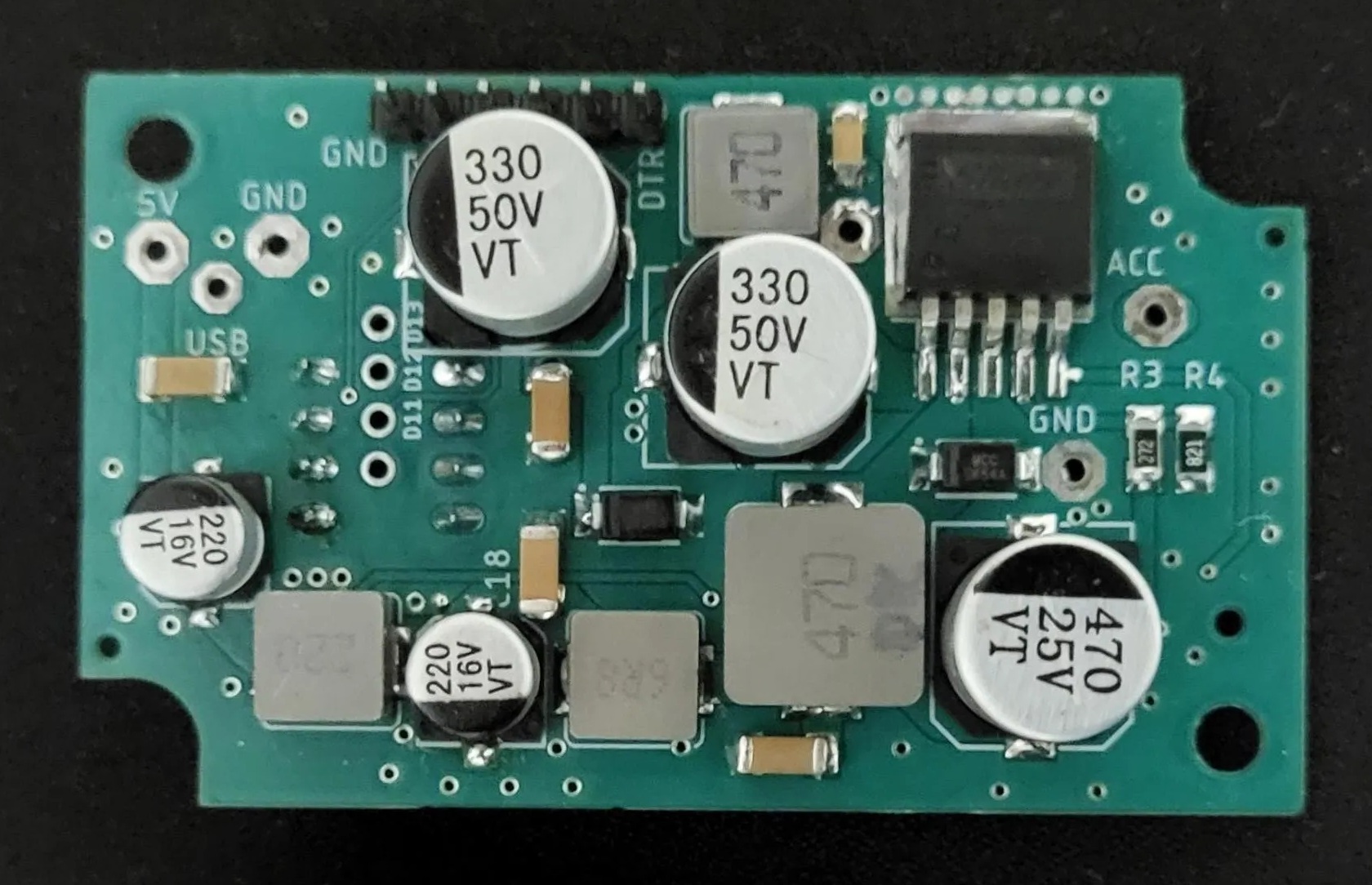
Why does it make sense to build your own power supply for the camera? First, unlike commercial models, the camera can keep recording for a while even after the engine is switched off.
Second, the consumption when the power supply is switched off is far lower than in commercial models — and we're not talking about 2 or 3 times lower. The result is better by a factor of 10 to 100. We're comparing milliamp-range consumption to tens of microamps. When parking for a long time, that can make the difference between the car starting or not.
Introduction
I built the first version of this power supply in 2023 — you can find it here. The new version came about once I realized, over time, what could be improved to make the power supply better.
I added filters on both the input and output of the LM2596M-ADJ converter, and adjusted the converter's output voltage to 5.3 V so that, after the voltage drop across the thin cable running to the camera, around 5 V arrives at the camera under typical current draw.
For more precise voltage measurement — since we're working in millivolts — I added the TL431 voltage reference.
Circuit Diagram
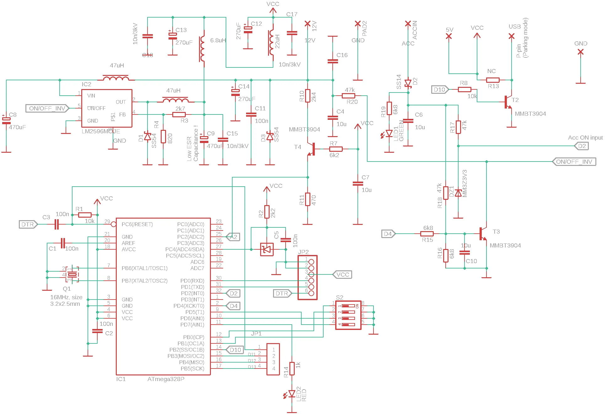
The schematic essentially consists of two sections: the switching voltage converter, and the control and indication circuitry.
The converter used here is a Chinese clone of the LM2596M-ADJ, which my tests showed actually has a lower OFF-state current draw than the original — roughly 2 to 3 times lower. (None of the 5 original ICs I tested, bought from DigiKey, met their datasheet-specified values!) On top of that, the Chinese clone costs a fraction of the original's price. The downside is a lower switching frequency than the original — 150 kHz for the original versus 56 kHz for the clone. In our case that doesn't matter, since the camera's current draw isn't very high.
Operation
When the 12/24 V supply voltage is applied, apparently nothing happens — and that's exactly how it should be. The converter enters the OFF state, or more accurately a standby state, where it waits to be switched on. Consumption in this state is around 30 to 70 µA, depending on the individual part and the supply voltage (12/24 V); on a 12 V on-board system it's typically under 50 µA.
When the on-board voltage arrives at the ACC pin, transistor T3 turns on and the LM2596M-ADJ converter starts working. Its output is set to approximately 5.3 V, and this voltage is fed to the camera through a dual filter. The same voltage also powers the MCU. Once the MCU has started up, it continuously monitors the presence of voltage on the ACC pin, while also measuring the on-board supply voltage through the R10/R11 voltage divider.
The presence of ACC voltage is indicated by LED1. A drop of the voltage below the set threshold is indicated by LED2. The turn-off voltage threshold and the delay before the camera is switched off after the engine is turned off are set using the 4-position DIP switch S2.
Pin D10 lets cameras with a "Parking Mode" feature switch into that mode.
PCB
You can download the double-sided PCB, designed in Eagle, in the Download section. The board is 1 mm thick, not the standard 1.6 mm! (The enclosure is designed specifically for this thickness.)
For easier handling, it's better to first populate only the side of the board with the MCU, then burn the bootloader, and only after that populate the other side of the PCB, where the filters are located. Of course, with Chinese manufacturers you can also order the PCB with one side already assembled, which makes things easier if you don't have much experience soldering SMD components.
Firmware
First, we need to burn a bootloader onto the MCU. I explain what that is and how to do it in the Band Decoder project's Firmware section. The pins used for burning the bootloader — RST, 11, 12 and 13 — are marked on the board.
Once the bootloader has been burned successfully, you can upload the current firmware to the MCU — you can download it in the Download section below.
Enclosure
You can download the .stl files and 3D print the enclosure yourself — the files are available in the Download section below.
The cover is designed for a 1 mm PCB! Use a print material suitable for in-car use, such as ASA, ABS, or similar materials that can withstand hot and cold conditions all year round. (Another advantage of the ASA I used is that you can glue or post-process the print with acetone.)
Insert a short piece of transparent filament into the LED hole, or cover it from the inside with transparent adhesive tape.
Secure the cable using self-fusing silicone tape (also sold as self-amalgamating or self-vulcanizing tape) — there are openings on both sides of the cover for it.
Settings
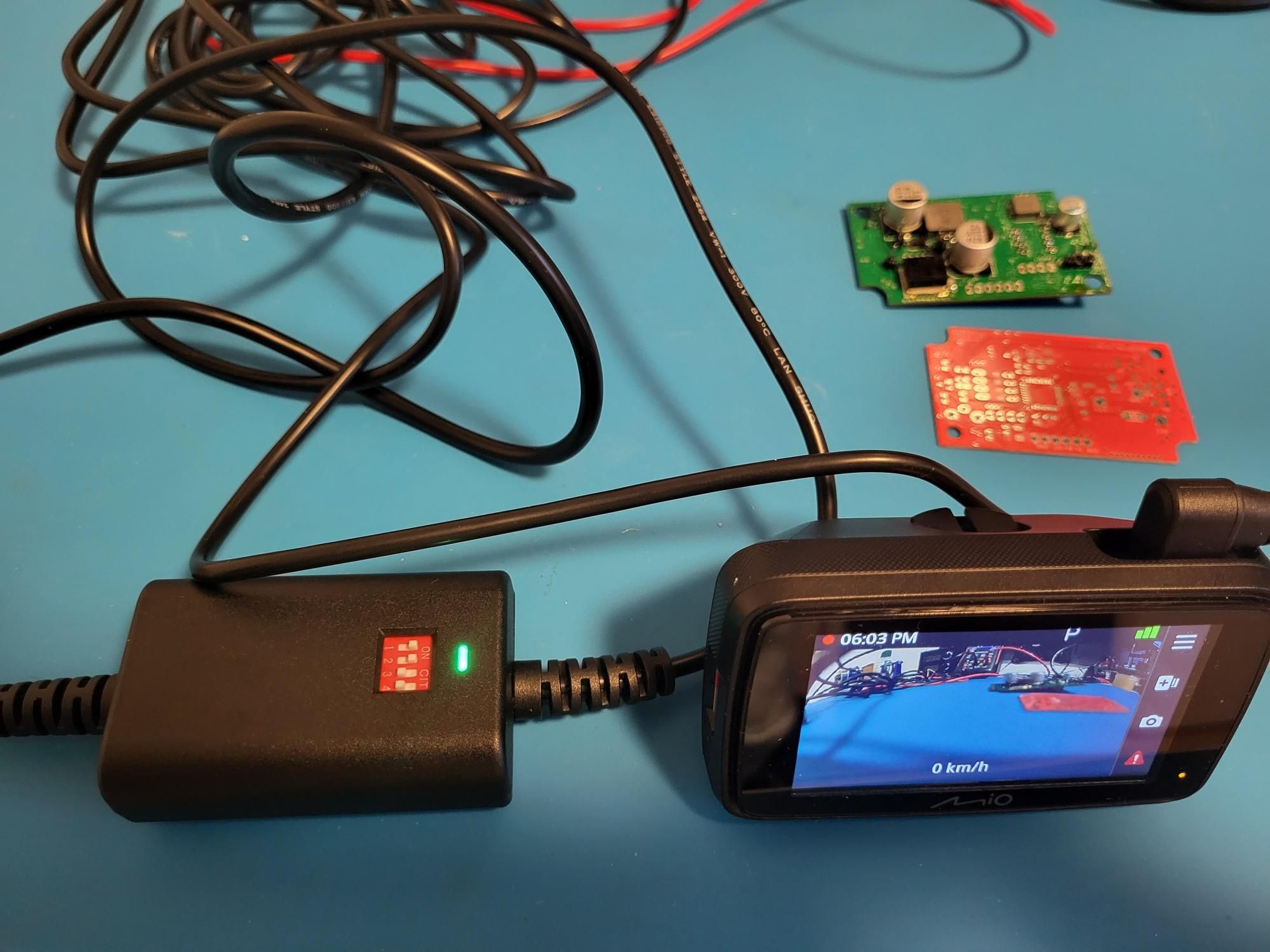
Settings are made using four small DIP switches.
S1 / S2 — voltage threshold selection (12 V system)
S1 S2 Voltage threshold
HIGH HIGH 12.2 V
LOW HIGH 12.4 V
HIGH LOW 12.6 V
LOW LOW 12.7 V
Note: when a 24 V system is detected, the threshold is multiplied ×2.
S3 / S4 — parking time selection
S3 S4 Parking time
LOW LOW 5 minutes
HIGH LOW 1 hour
LOW HIGH 3 hours
HIGH HIGH 24 hours
