This page is currently being written — content is added progressively as the project is documented.
ESP32 · Touch 2.4"Rotator Interface — ESP32 Touch 2.4
Control a YAESU antenna rotator using a touchscreen display or from a PC over WiFi or USB, with the option to connect a weather station and rotate the antenna in response to wind.
Overview
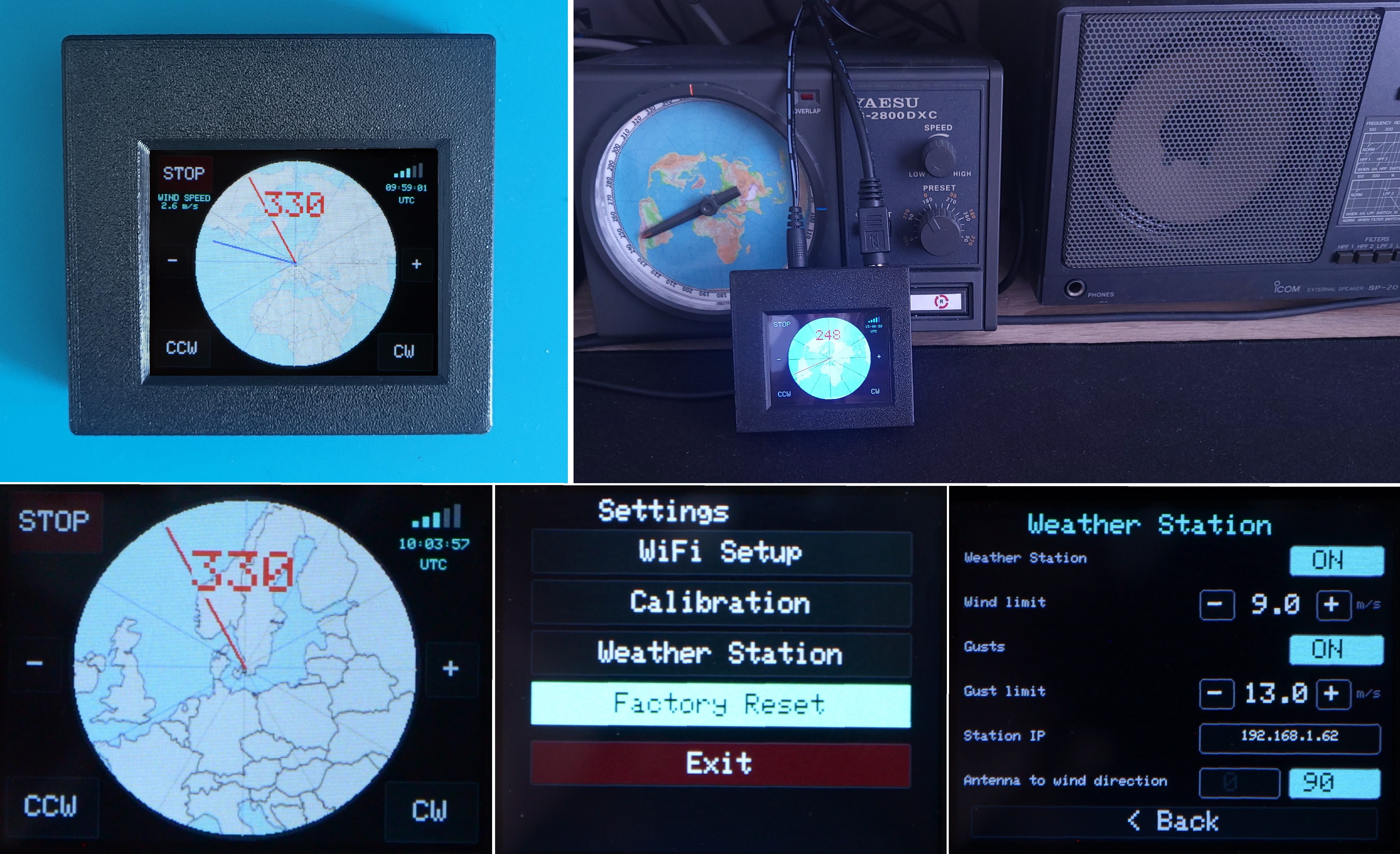
After getting familiar with the ESP32-S3 UNO development board, I decided to try building my own project around the ESP32-S3 module. It was also the first time I used a touchscreen display, and the first time I used a stencil for soldering. It's an experimental project with a minimal set of components — I chose parts I had already worked with in previous projects, to avoid any unwanted surprises.
Once I managed to get the touchscreen display working, I started adding further functions to the project.
Key Features
- 2.4" touchscreen display
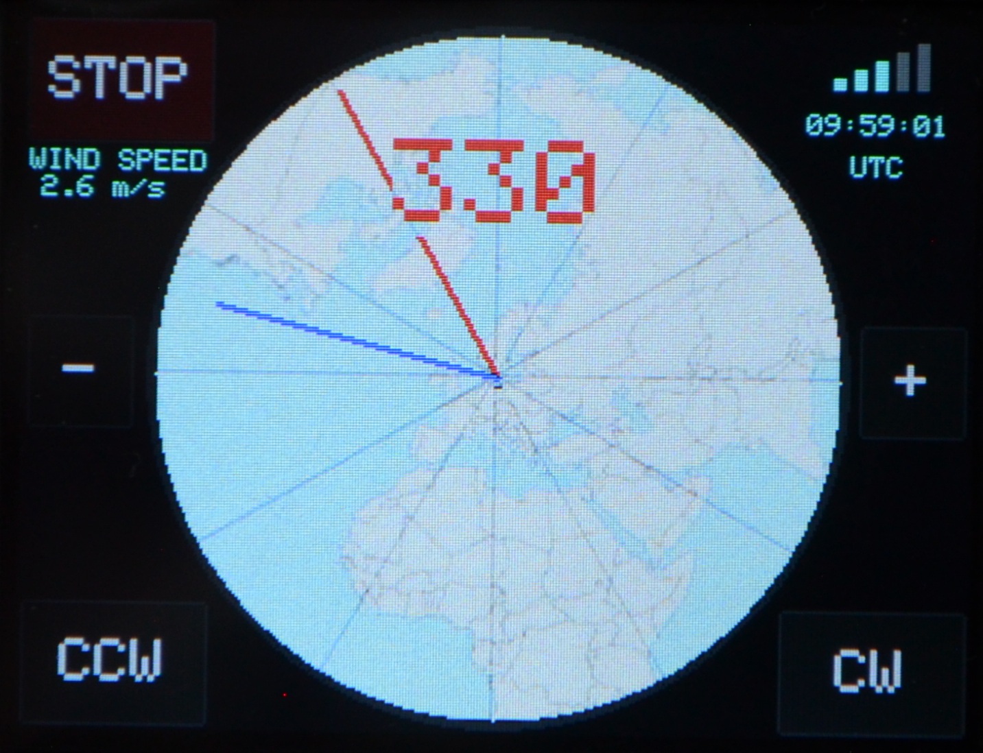
- Needle-style display of current azimuth, target azimuth, and wind direction
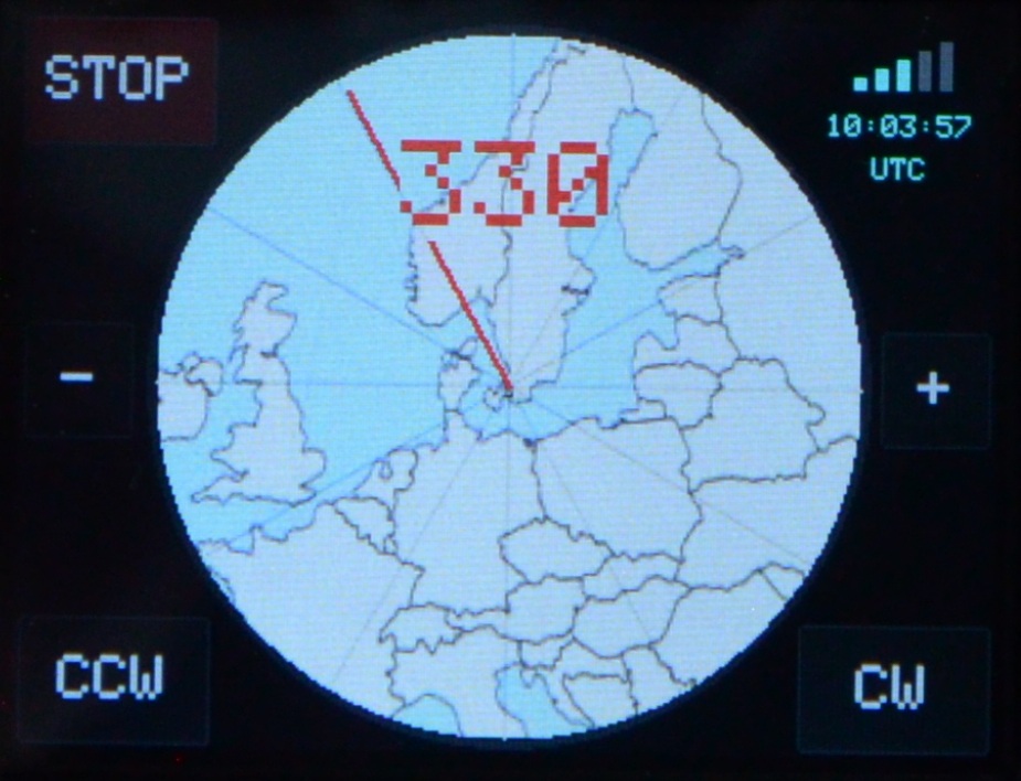
- Zoomable circular map shown in the background
- WiFi signal strength measurement
- UTC time display
- Wind speed and direction display
- Azimuth entry by tapping the map or using CW / CCW buttons
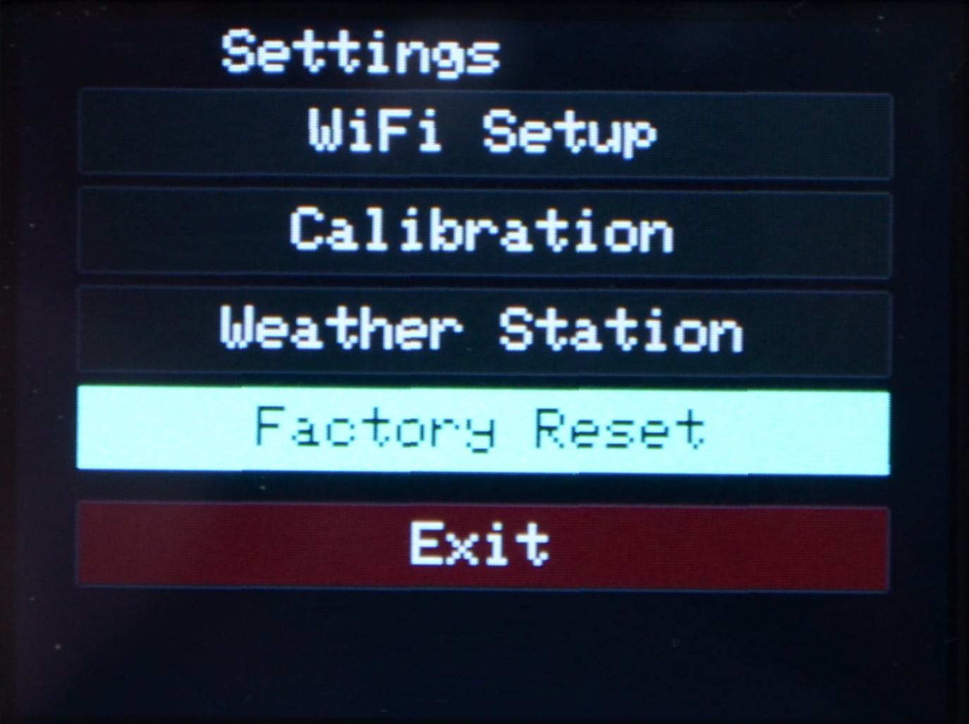
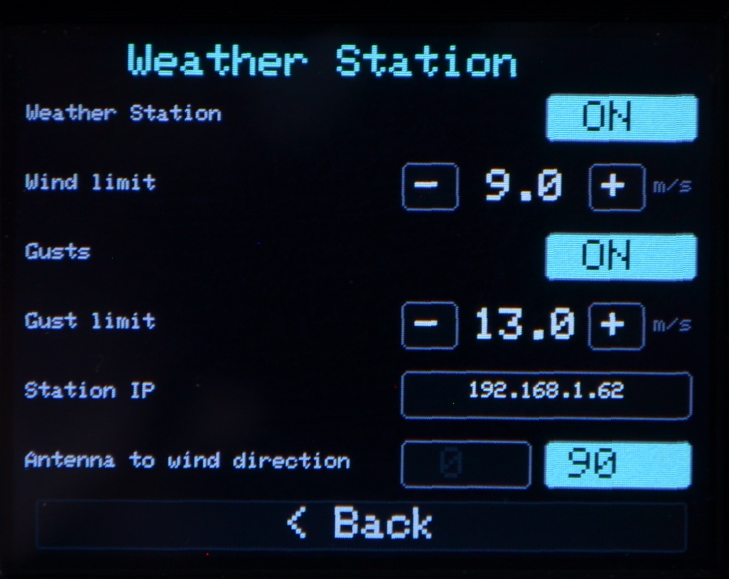
- User menu for WiFi setup, calibration, and weather station configuration
- Software motor protection
How It Works
The core operating principle is the same as in the ESP32 Simple version. The rotator control unit is connected to the interface board using a cable. Its control inputs (one for each rotation direction) are each connected to a transistor. When one of these inputs is pulled to ground through its transistor — never both at the same time — the rotator starts turning in the corresponding direction. Each transistor is switched on by its base, which is connected to one of the ESP32 digital outputs.
Another signal line is used to determine the antenna azimuth. This signal comes from the rotator's internal potentiometer, which provides a voltage of approximately 0 to 4 V, depending on the antenna position. This voltage is connected to the ESP32-S3 analog input through a voltage divider. The firmware continuously measures this voltage and calculates the current azimuth of the antenna.
PC control logic
The PC is connected to the ESP32 either via USB or over WiFi. A control application running on the PC (for example, PstRotatorAZ) sends commands specifying the target azimuth.
The firmware compares the target azimuth with the current antenna position and decides which output should be activated. This turns on the corresponding transistor, which pulls the associated rotator control input to ground, causing the antenna to rotate in the required direction until the desired azimuth is reached.
Touch control
The interface can also be controlled by touching any point on the map. The map can be zoomed in four steps — at maximum zoom it shows the whole world, while at minimum zoom it shows only part of Europe. Another option is control using the CW, CCW, and STOP buttons.
Circuit Diagram
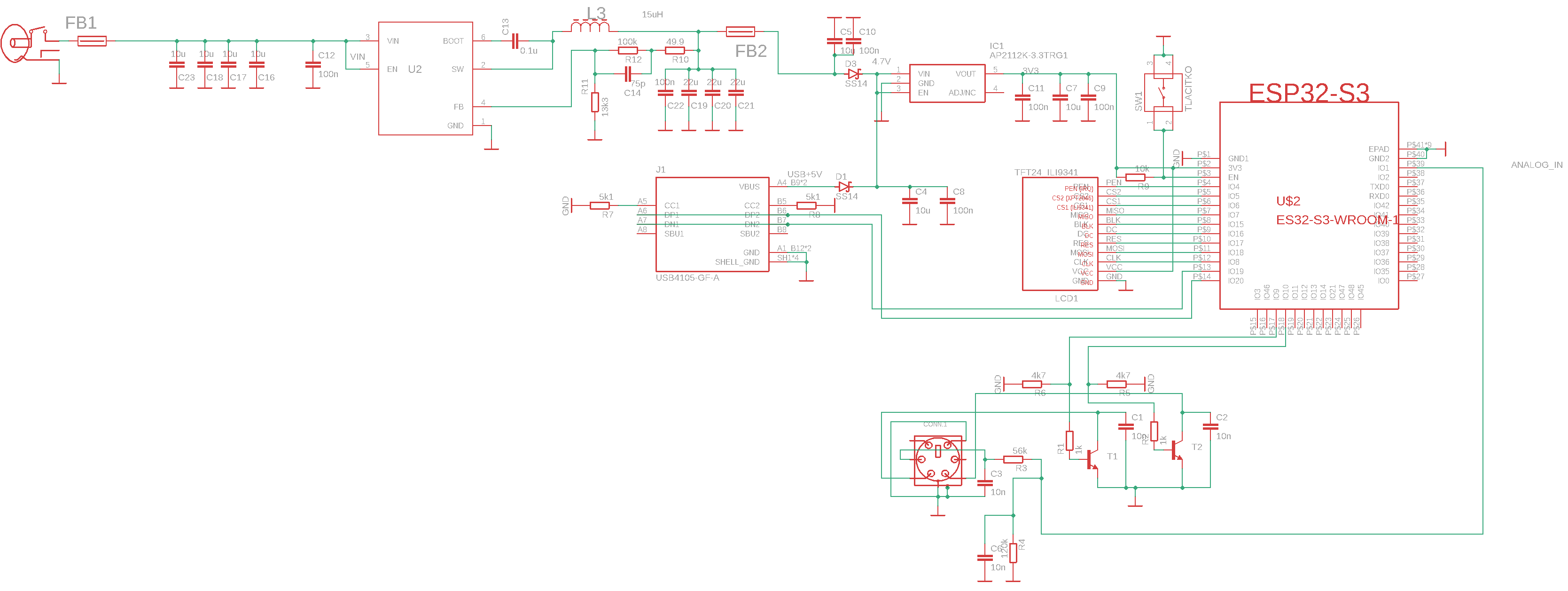
The circuit diagram is fairly simple. The basic operating principle is straightforward and is based on measuring the input voltage from the rotator's potentiometer, which is fed through the R3/R4 voltage divider. This divider ensures that the voltage at the MCU input pin never exceeds 3.3 V. The direction of rotation is controlled from the MCU output — the MCU's control voltage is applied to the base of T1 or T2. Transistors T1/T2 pull the Yaesu controller's input pin to ground, which causes the antenna to rotate in one direction or the other. Control and display are handled by the touchscreen display, which is connected directly to the MCU without any additional components. The USB-C connector, used for programming and optionally also for control (when WiFi is not used), is connected in the standard way to pins IO19 and IO20. All other components ensure the MCU operates under the correct conditions.
The supply voltage from the ham shack (typically 13.8 V) is fed into a switching converter whose output is approximately 5 V. Ferrite beads are placed at the converter's input and output to reduce interference. The voltage is then further reduced to 3.3 V by the AP2112K linear regulator. This regulator has enough power dissipation capacity to supply both the MCU and the display used here. If you want to use a larger display, its power supply needs to be handled separately.
PCB
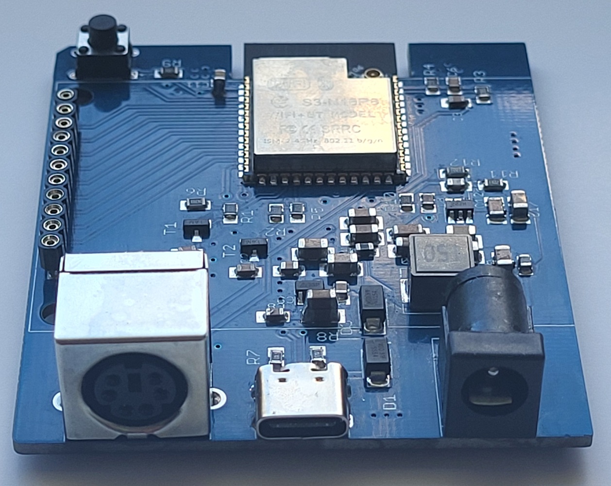
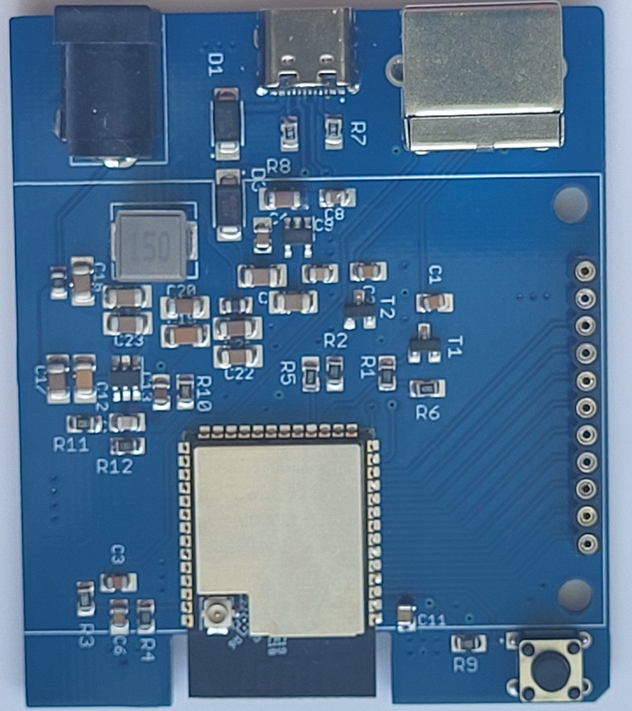
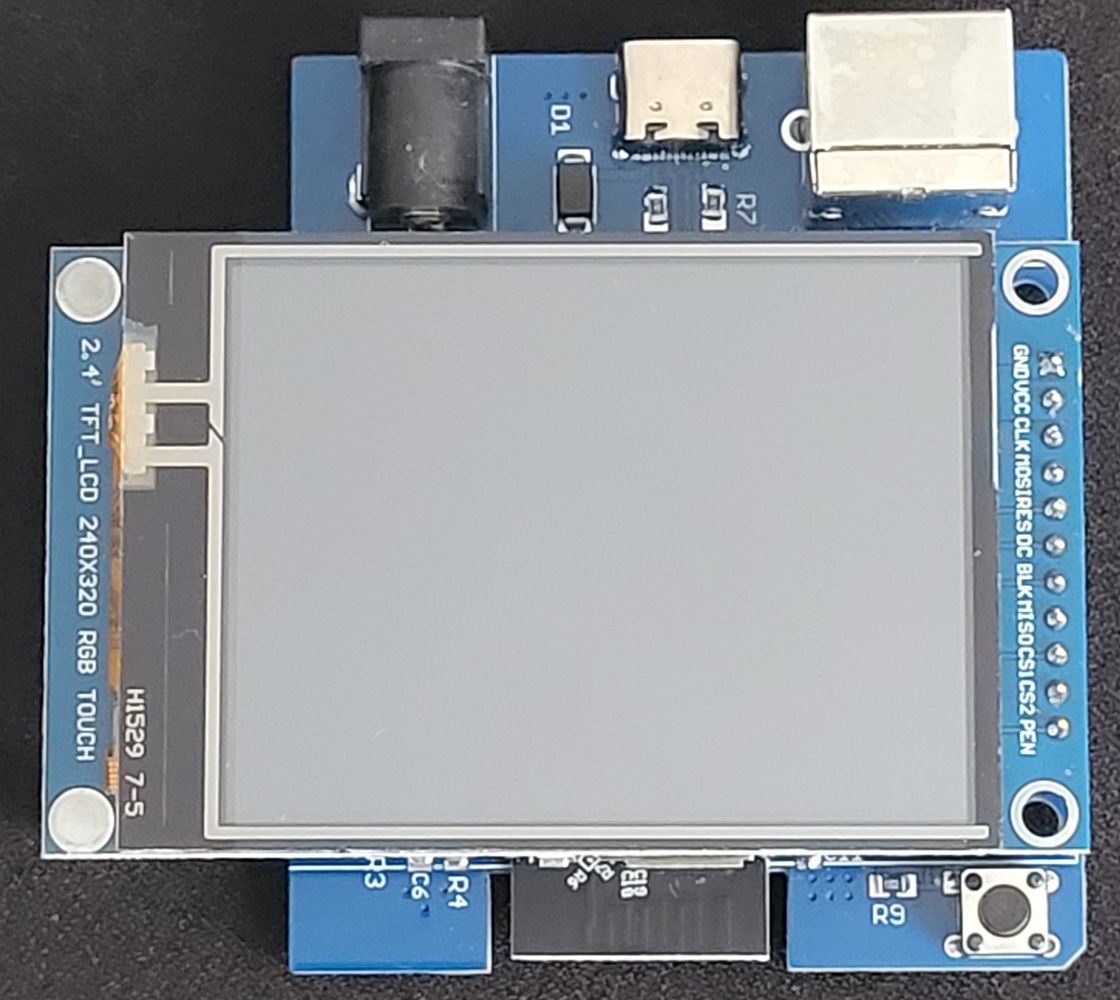
The PCB is double-sided, with components populated on one side only. The PCB, designed in EAGLE, can be downloaded in the Download section below.
I'd like to point out that the ESP32-S3 module has GND pads on its underside that must be soldered to the PCB. This means you can't use hot-air soldering, where the hot air only comes from above, from the components side. Even a soldering station with bottom-side preheating won't provide enough heat — by the time the temperature between the module and the PCB reached the required level, the module would most likely already be destroyed.
This time I used an electric hot plate, 200×200 mm, which I bought for 50 EUR from Germany (via AliExpress). To get the optimal amount of solder on the pads, I also ordered a stencil together with the PCB. I decided to try using a stencil because, when ordering PCBs with components pre-assembled, the price goes up by a few EUR/USD for every "special component." Almost all semiconductors — and even some common SMD resistor values — count as "special components," so these fees alone can add up to several tens of euros. Manufacturing a PCB plus a stencil is still relatively cheap (even though EU officials have decided to heavily tax all imports from China and add fees on every shipment, since after a series of their own decisions they've been unable to secure economically viable manufacturing within the EU itself — it's interesting that there's always money found for armament, promoting gender equality, promoting green energy, and technology for monitoring and suppressing expressions of discontent).
So I wanted to try something new that could also come in handy in the future. It took a bit of skill, but I managed it. I can send over the procedure on request, but I won't go into detail here — that deserves its own separate paragraph or a short article.
