ESP32S3 based WiFi / USB Rotator Interface
Control a YAESU antenna rotator from a PC over WiFi or USB — simple version, no buttons, no displays, just a clean PC interface added on top of the original controller.
Overview
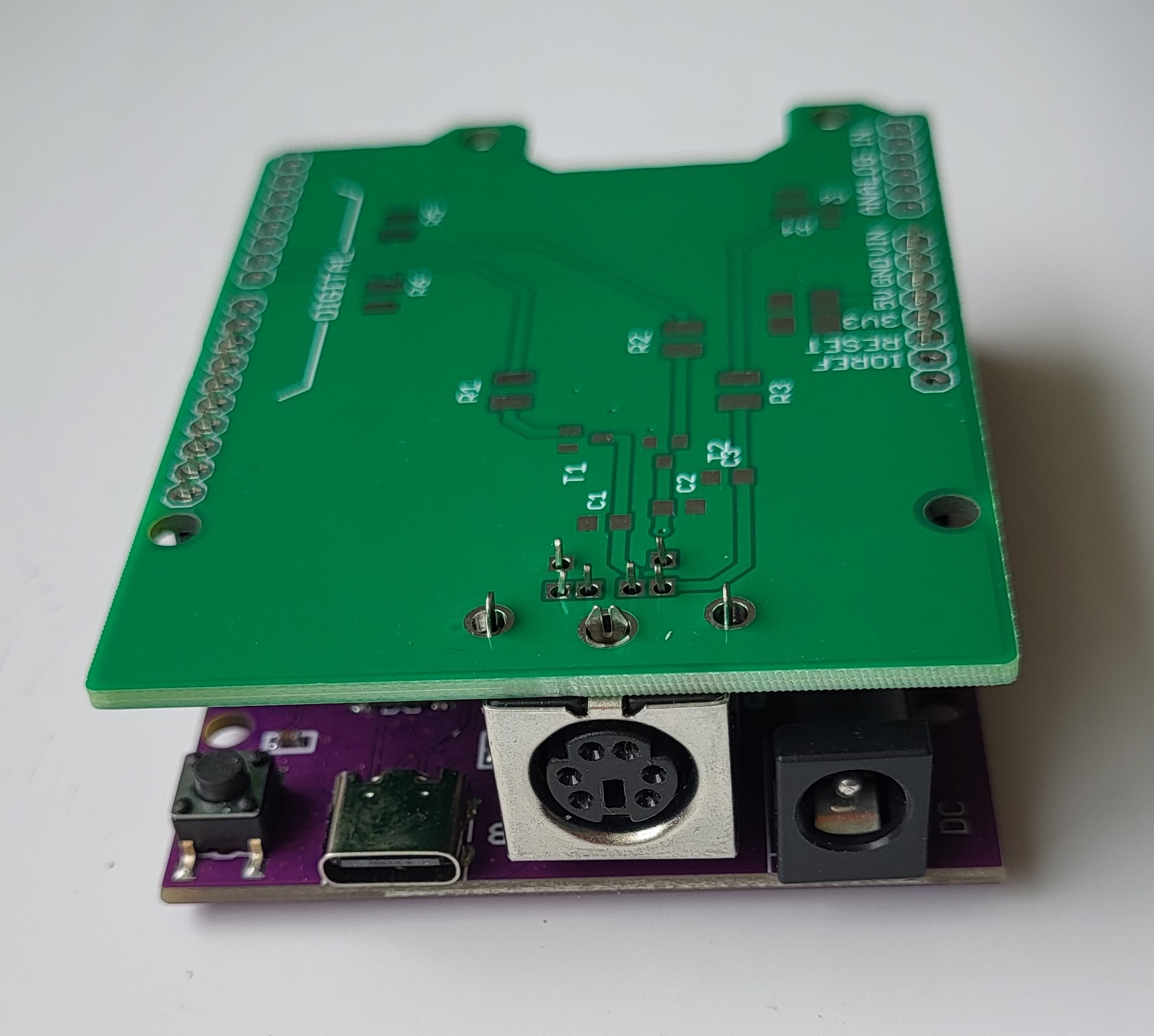
This project came about because I wanted to control my YAESU rotator over WiFi. Up to that point I had been working with Arduino, but ran into the problem of connecting an Uno to WiFi at a reasonable cost. At the same time, I wanted to try the ESP32-S3 module, which is several times more powerful than the Uno, but unlike the Arduino, works with 3.3 V logic.
The ESP32-S3 exceeded my expectations by a wide margin, and I now use an interface that has a touchscreen display, can connect to my weather station, and in case of strong wind can rotate the antenna to present minimal resistance to it.
I started out, however, with exactly this module — the result of a small but necessary hardware modification to a project originally based on the Arduino UNO.
I used the device for only a few weeks, but given the price of a ready-made ESP32-S3 module with WiFi and the small additional PCB that needs to be manufactured, I decided to publish this project because it might be useful to someone. I have several bare PCBs (without components) available, which I can provide for a symbolic price of 1 EUR (USD) plus shipping. The PCB is freely available for download in the Download section below.
Supplies
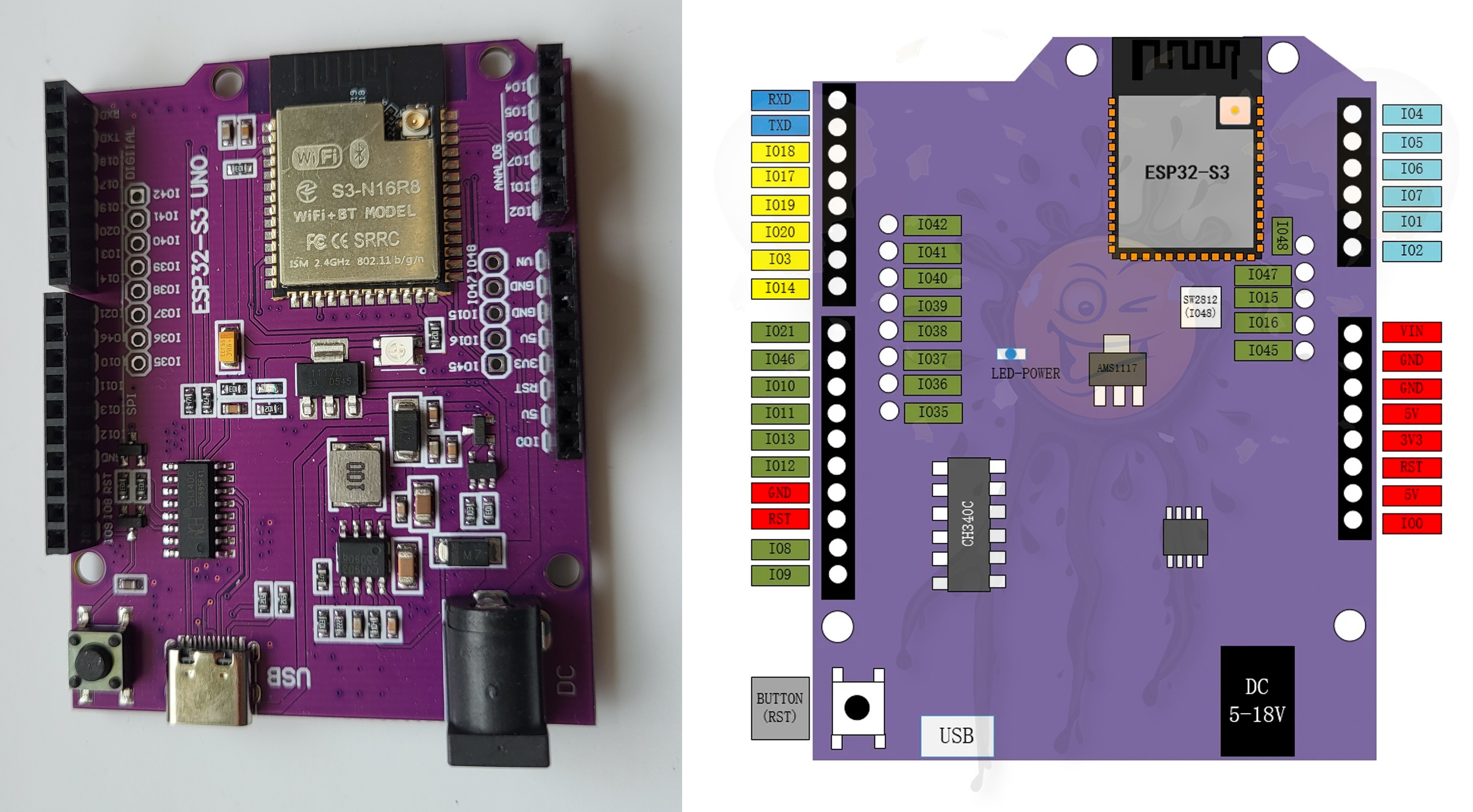
- ESP32-S3 development board (shown above)
- Custom PCB by SA7KZA — schematic and board files in the Download section below
- 2× NPN transistors (MMBT3904 or similar — almost any common small-signal NPN transistor will work)
- 2× Resistors — 1 kΩ (1206) R1, R2
- 2× Resistors — 4k7 (1206) R5, R6
- 1× Resistor — 56 kΩ (1206) R3
- 1× Resistor — 120 kΩ (1206) R4
- 3× Capacitors — 10 nF (0805)
- 1× Capacitor — 1 to 10 µF (0805) (optional, not strictly required)
- 1× PS/2 connector (6-pin socket)
- 1× 6-pin male-to-male cable (Mini-DIN / PS/2 extension cable)
How It Works
Connection to the rotator
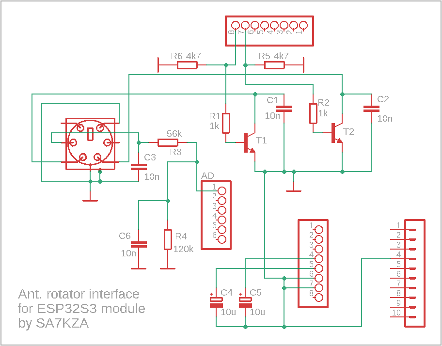
The rotator control unit is connected to the interface board using a cable. Its control inputs (one for each rotation direction) are each connected to a transistor. When one of these inputs is pulled to ground through its transistor — never both at the same time — the rotator starts turning in the corresponding direction. Each transistor is switched on by its base, which is connected to one of the ESP32 digital outputs.
The schematic here differs from the Arduino version. Under normal operation you won't notice anything, but a problem appears once the interface is powered off. The internal structure of the Arduino UNO and the ESP32-S3 UNO module is different — the ESP32-S3's pins allow some leakage voltage from the potentiometer input to reach the bases of T1 and T2, and this can make the controller's output relays start switching randomly. To prevent this, resistors R5 and R6 were added to the circuit, pulling this leakage voltage down to a level too low to turn on T1 and T2.
Another signal line is used to determine the antenna azimuth. This signal comes from the rotator's internal potentiometer, which provides a voltage of approximately 0 to 4 V, depending on the antenna position. This voltage is connected to the ESP32-S3 analog input through a voltage divider formed by R3 and R4. The firmware continuously measures this voltage and calculates the current azimuth of the antenna.
PC control logic
The PC is connected to the ESP32 either via USB or over WiFi. A control application running on the PC (for example, PstRotatorAZ) sends commands specifying the target azimuth.
The firmware compares the target azimuth with the current antenna position and decides which output should be activated. This turns on the corresponding transistor, which pulls the associated rotator control input to ground, causing the antenna to rotate in the required direction until the desired azimuth is reached.
Construction and Assembly
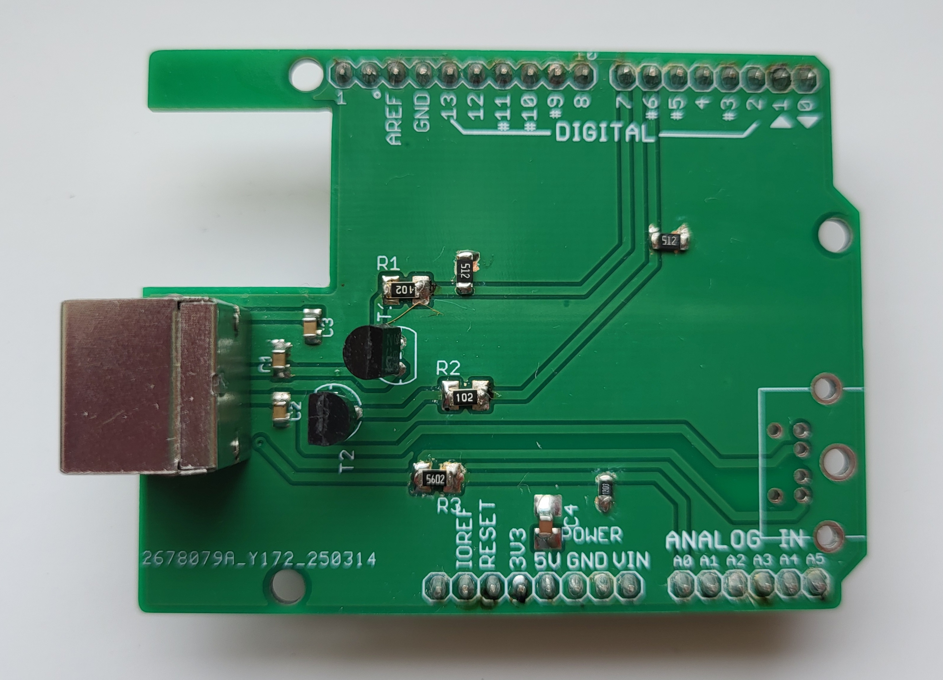
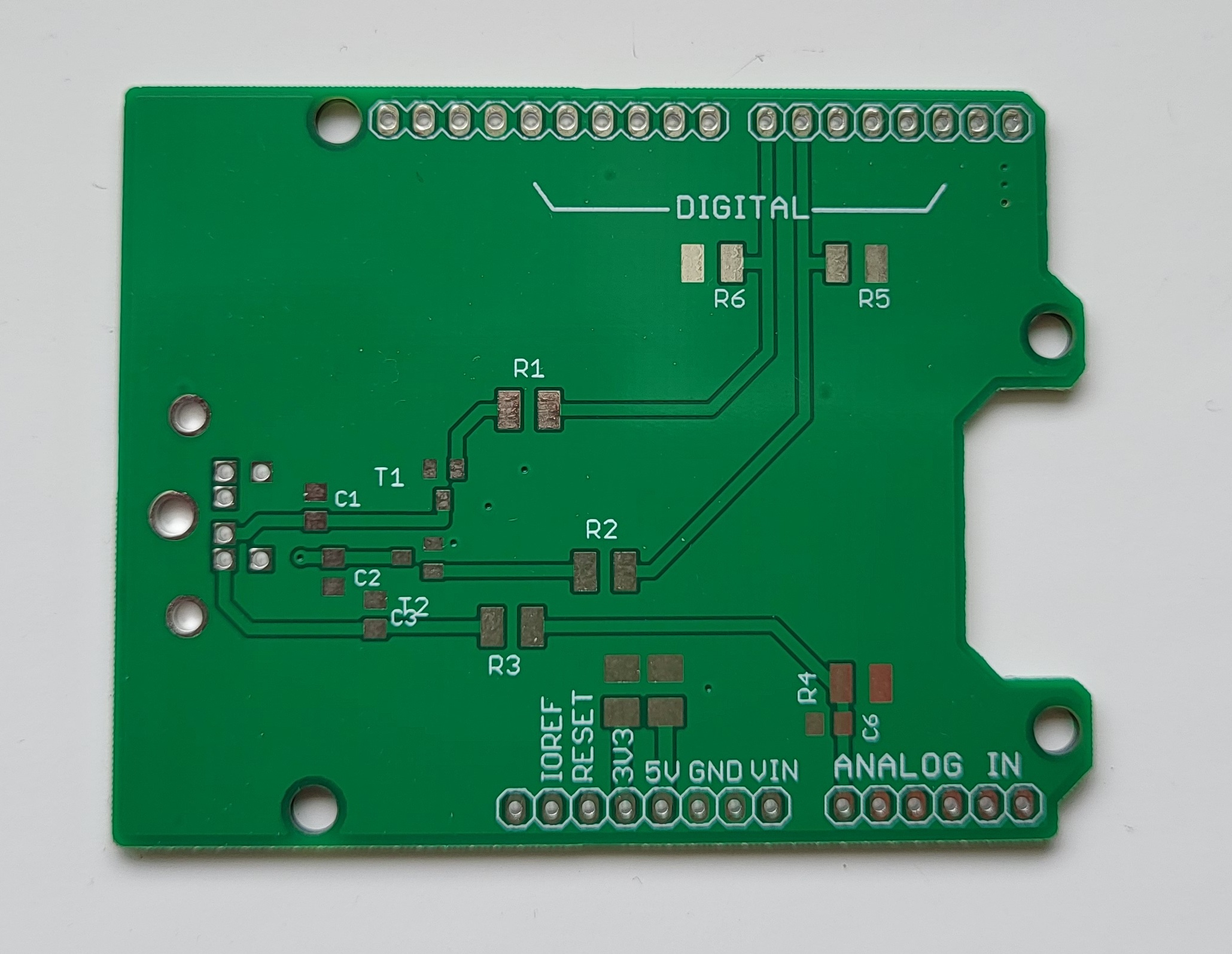
For a few weeks of testing I modified the PCB I'd used in the Arduino project (image on the left). For the final version, I designed the PCB shown on the right. The two boards are electrically identical, but the final version is designed to keep the device as low-profile as possible, which is why it uses SMD components. Pay attention to connector orientation — the connector is mounted on the underside of the PCB. On the right side of the board there's a cutout so the GND plane doesn't overlap the ESP32-S3 module's WiFi antenna.
To connect the interface board to the ESP32-S3 UNO, standard 2.54 mm pin headers can be used (single-row male or female headers commonly sold for Arduino projects). Short pieces of wire can also be used if preferred.
Firmware
The code was developed using the Arduino IDE and tested with PstRotatorAZ control software and a YAESU G-2800 antenna rotator.
The firmware implements the GS-232 protocol, making it compatible with most YAESU antenna rotators that support this standard.
In most cases, the system should work on the first power-up. However, some fine-tuning may be required, as each rotator and controller combination behaves slightly differently. Cable length, wire diameter, and mechanical tolerances can influence the measured values.
Configuration
All configuration parameters are located at the top of the source code, where each setting is clearly described.
USB-only operation
If you are not using WiFi, the only required adjustment is calibration of the potentiometer end values. These are typically around 0 V and 4 V, but the exact values depend on the individual rotator and controller. A voltage divider is included on this line, since the voltage at the MCU input must never exceed 3.3 V. Enter the values measured at the MCU pin into lines 44 and 45 — first with the antenna rotated to 0°, then to 360°. The firmware automatically calculates the corresponding value for 450° if you're using a rotator's full extended range.
44 #define ADC_MV_0DEG 10 //mV at 0
45 #define ADC_MV_360DEG 2200 //mV at 360
WiFi operation
If you're using WiFi, additional network settings must be configured:
- Set your WiFi network's SSID on line 17.
- Set your WiFi network's password on line 18.
- Set the interface's IP address on line 20, according to your local network (default: 192.168.1.186 — choose an unused address).
- Set your router's (gateway) address on line 21 (typically 192.168.1.1, or 192.168.50.1 on newer ASUS routers).
- Other network parameters (subnet mask, DNS) can also be adjusted on lines 22–23 if your network requires it.
- In the PC control software, set the TCP port to 2823.
Once these parameters are set, the interface is ready for operation via WiFi.
Source Code Overview
This firmware implements a fully featured antenna rotator controller compatible with the YAESU GS-232 protocol, supporting simultaneous control via Ethernet (TCP port 2823) and USB/Serial.
The control logic is based on a robust state machine, ensuring smooth and safe rotator movement. This includes:
- Enforced delays when changing direction (CW ↔ CCW)
- Automatic selection of the shortest rotation path, including support for extended-range rotators (e.g. 450°)
The antenna position is continuously measured using an analog position sensor, filtered by averaging, and converted into precise azimuth values in degrees.
Multiple layers of safety protection are implemented, including:
- Motor stall detection
- Maximum rotation time limits
- Infinite rotation prevention
- Verification of actual mechanical movement
If repeated faults occur within a defined time window, the controller enters a hard lockout mode with an extended cooldown period.
